Earthing
Earthing for Audio
The following is taken from an article published in the Nov/Dec 2005 issue of LineUp by Peter Thomas, Managing Director of the Professional Monitor Company, with his kind permission.
At the outset, I need to make clear that there are no references to PMC loudspeakers at all (except in this introduction). Neither are there any black and white answers to earthing issues, nor easy fixes to the numerous problems caused by earthing configurations. If this is your expectation then stop reading right now to avoid disappointment. The management also reserves the right to oversimplify situations for the benefit of clarity, teach their grandmothers to suck eggs and keep engineering detail to a minimum. Insomniacs are advised to keep this article handy by their bedside.
The purpose of this brief tour of earthing is to raise awareness of what causes hum and noise in audio systems, and ultimately produce a simple list of logical things to check to isolate and avoid problems.
Mains Earth
Before we launch headlong into earthing, it’s quite important to appreciate where the mains earth originates from and what it’s actually there for.
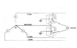
Figure 1 shows an extremely simplified circuit diagram of a three phase generator. Note that there are three live (L) outputs (marked ‘Line’ on the diagram), whilst the neutrals (N) are all tied together. Note also that the neutrals are connected to ground. This will become an important factor later on. The earth’s primary role is naturally for safety. However, in audio systems it also has to provide noise rejection through shielding against low and high frequency noise (hum and interference). For the audio professional the dilemma with this is that its safety role often conflicts with the goal to keep noise at a minimum… but this is not – under any circumstances – an excuse to remove a safety earth to cure noise problems.
Noise Sources
There are two types of noise that need rejecting: low frequency noise such as mains hum (50Hz) and buzz (100Hz), plus high frequency noise such as radio interference, digital breakthrough, thyristor noise (from lighting dimmer circuits), and basically anything that switches at high frequencies. Clearly, high gain circuits such as mic and guitar preamps are particularly vulnerable. High frequency interference is on the increase, and becoming harder to eradicate. One of the delights of trying to find a solution to eliminate both low frequency and high frequency sources of noise is that the cure for one often increases the other – but then you wouldn’t expect anything less! There are many ways that these noise sources find their way into our audio circuits. The five primary routes are: induced currents, capacitive-coupled currents, loop currents, fault currents (including dirty earths), and finally multiple earth paths. Did I say this was going to be easy?
Induced and Capacitive Coupled
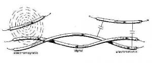
Take a look at Figure 2. This shows how induced and capacitive-coupled currents cause noise. Here we see a balanced cable in the foreground lying next to two external cables. Low frequency noise is induced electromagnetically into the audio cable (left of picture), and high frequency noise is capacitively (electrostatically) coupled into it (right).
These are two good reasons for keeping audio cables as far away as possible from other cables carrying potential noise sources – such as cables carrying mains or digital signals.
Loop Currents
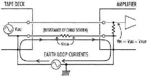
Figure 3: A classic ground loop situation
Figure 3 is an example of how loop circuits act like detectors for noise when connecting two pieces of unbalanced equipment together. In this example, both pieces of equipment are plugged into the mains and receive a (safety) earth which also provides a link between the two chassis. Additionally, the screen of the unbalanced cable also provides a connection between the two units forming a ‘ground loop’ with the mains earth. The noise source only produces an audible problem (VHUM) when the loop is present. If no loop was formed then no circuit would be formed for the noise source, preventing the noise current from flowing and VHUM would not exist. But no, we can’t lift the mains earth to break the loop and cure the problem!
Fault Currents and Multiple Paths
Mains earths will often carry high fault currents (in the event of poor or faulty equipment being connected to it) and will therefore be termed ‘dirty.’ Mains cables are also commonly installed as a ring main – i.e. in a loop – and cause circulating noise currents with multiple paths being taken by the fault currents. Audio equipment placed inside an area where fault currents are flowing via different paths will be susceptible to the radiated field from the mains earth cables, chiefly through induction, and large hum fields will be present. Moving cables in this instance will not completely solve noise problems. Having painted such a negative picture of the problems we face, and before we all give up and retire to the South of France (always an attractive option) let’s take a look at the solutions available to us to improve the above situations and minimise noise.
Clean Earths
The problems produced by dirty mains earths have lead many broadcasters and studios to provide a ‘Clean Earth’ in their installations. This is sometimes also referred to as ‘Programme Earth’ (mainly by broadcasters) or ‘Technical Earth’ (by broadcasters and studios) – just to confuse everyone.
In these installations this ‘clean earth’ is kept free of fault currents, enabling it to provide the screen to the audio circuits. Clean earths are wired in a star from the incoming earth to the building. In other words, a single cable is routed to each technical area, rather than being looped around the building as is the normal way with standard mains distribution. Each mains socket is then star wired individually back to the incoming clean earth to the technical area. This reduces the incidence of hum loops and also keeps any fault currents from upsetting the entire building as they are routed directly to the incoming mains earth to the building.
The down side of clean earths (apart from cost) is that they must be kept separate from the mains earth distribution in the building, otherwise the combination of multiple paths will be a source of considerable noise problems (and heartaches).
This is not to say that the mains earth distribution cannot be wired to the same standards as a proper clean earth arrangements – and in many installations the need for a separate clean earth distribution has been avoided by adopting the same distribution techniques. For example, Metropolis Studios in London run screened earth cables to each studio from the incoming mains feeder.
In situations where equipment is being rigged in premises not under your control, plugging all the equipment into a single mains outlet (preferably with the benefit of a distribution board) will avoid most problems inherent with a dirty or poor mains earth.
Lifting Earths Safely
There are instances where breaking a mains earth loop is required to solve a hum problem. The use of an isolating transformer is the only solution to avoid compromising the safety of the equipment.
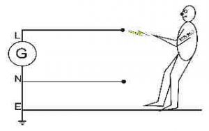
Figure 4: The potential shock hazard
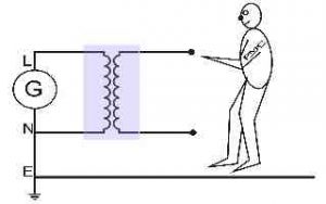
Figure 5: An isolating transformer prevents the shock hazard
Consider the scenario where the mains earth has been lifted from a piece of equipment, and a fault subsequently develops in which the mains Live becomes connected to exposed metalwork. Figure 4 illustrates that a shock can be received from the Live mains supply because a circuit is made back to Neutral via the earth – as per Figure 1 where the neutral is earthed at the generator – and so a potentially lethal current flows through the body.
Figure 5 illustrates that if that same piece of faulty equipment was connected via an isolating transformer, there would no longer be a circuit back to earth. No current would flow and no shock would be received because the transformer provides the break in the circuit. The only golden rule to remember is that you must connect only one piece of equipment per isolating transformer.
The downside of this approach – lifting the mains earth combined with an isolating transformer – is that in removing the mains earth reference from a piece of equipment you may well open it up to high frequency noise pick up through the reduced effectiveness of its shielding. Also, high frequency noise can capacitively cross the isolating transformer’s windings and enter the equipment via its own transformer.
Balanced and Unbalanced Circuits
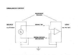
For the purpose of reducing noise, unbalanced circuits should be avoided if at all possible. Figure 6 shows how the screen of the interconnecting cable is the return path for the audio, and so it cannot be removed or disconnected. However it also forms part of a ground loop with the mains earth connection between the two pieces of equipment. Nevertheless, if the mains earth is clean, both pieces of equipment are plugged into adjacent outlets, and the audio interconnects are not routed near sources of noise then usually this work wells.
Figure 6: An unbalanced connection
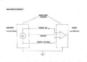
Figure 7: A balanced connection
In the case of the balanced circuit shown in Figure 7, the screen of the interconnecting cable is no longer part of the audio circuit, and although forming an additional link between the two pieces of equipment along with the mains earth connection, no noise current is flowing in the audio go and return feeds. Even in a noisy environment, this circuit should be noise free as the audio is balanced around the earth, and any earth current noise is not ‘seen’ by the audio circuits.
To provide greater rejection and higher immunity from external noise in high gain circuits or in areas of high potential noise sources, connecting equipment together with ‘star quad’ cable will reduce noise problems significantly – albeit at additional cost. Its four conductor construction provides over ten times the noise immunity of ordinary cable from induced and capacitively coupled noise sources.
Electronically Balanced
The rejection of noise by a balanced circuit relies on two mains things: the accuracy of the balance of the equipment’s input and output circuits – the common mode rejection – and that the circuits are earth free.
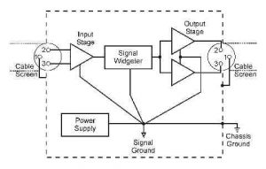
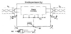
When audio transformers were the common means of achieving balanced inputs and outputs they were truly earth free (as in the case of isolating transformers). However, as electronically balanced circuits are now standard in many products, a reference to earth is inherently present and provides an alternative path for noise to intrude into the audio circuits. Figure 8 illustrates the possible routes within a piece of equipment from both the output and input electronic balanced circuits.
Figure 8: Possible earth noise routes within electronically balanced equipment
In view of the above, electronically balanced circuits can still be prone to noise from multiple earth loops. Older equipment usually connected the shell of the XLR to the equipment chassis whilst pin 1 was connected to the internal 0 Volts reference for the electronics. For new equipment conforming to AES48-2005 (see Figure 9), pin 1 and the XLR shell are now connected directly to the equipment chassis.
So that XLR cables function with both topologies without causing hum and noise, pin 1 and the shell are best wired separately to avoid problems, allowing the equipment to determine whether they are linked or not. In other words, do not link pin 1 and the shell inside XLR connectors.
Figure 9: The AES48-2005 grounding recommendation.
Lifting Pin 1
In the situation where there is still a hum and noise problem, a common quick fix is to remove the earth connection to pin 1 in the XLR cable at one end. Although solving low frequency hum problems, this technique does compromise the screening and consequently can increase high frequency noise intrusion. It also causes problems if cables are extended by plugging two together – since the screen connection may be removed entirely. Rather than modifying cables by permanently disconnecting pin 1, an easier and more controllable solution is to make up some XLR barrels with pin 1 disconnected internally. These can then be connected in series with the XLR cable when required.
In Summary
Connect equipment to a known clean earth, or connect to common earth point. Don’t mix earths. Avoid unbalanced equipment. Use star quad interconnects in sensitive circuits. Re-site equipment and cables away from noise sources. Lift mains earths only with isolating transformers. Lift Pin 1 on XLR if all else fails. The overriding factor in trying to reduce noise problems is not to compromise the safety earthing in any way.
Further reading (“A Practical Interference Free Audio System” by Tony Waldron CADAC)

