Bright Eyes (Phantom checker)
This “Bright Eyes” device was described by Hugh Robjohns in this Line Up article (June/July 2006) and uses a circuit designed by Chris Woolf. A Bright Eyes can be a very useful tool to have during rigging or fault finding to check if an XLR cable has active microphone powering. It is simple to construct from this circuit diagram, all the components can be squeezed into a male XLR body.
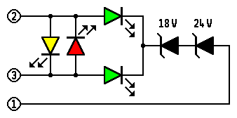
Circuit diag
P48 Phantom Power is the de facto standard. It is balanced power and the same positive voltage should be present on both signal lines (pins 2 & 3) with zero volts on the ground. The tolerance is +/-4V (44 – 52V). The Bright Eyes uses zener diodes to ensure that the green LEDs only light if the P48 is above 44V. The phantom supply series resistors limit the overall current. Both LEDs should light equally; one LED only suggests an open-circuit cable leg; no LEDs either no power or a broken screen (pin 1) connection.
A similar device could be made for the rarer P12 phantom by using a single 10V zener diode .
T12 Tonader Power is unbalanced and conventionally has +12V on Pin 2, zero on Pin 3 (though the voltages may not be referenced to ground). Reverse polarity versions have been used in the distant past. The Bright Eyes detects T12 with the yellow LED. The 180 ohm series supply resistor limits the current but it will be higher than the P48 one – the yellow LED glows brighter than the green ones. The red LED detects reversed powering – which may be due to crossed XLR connections. The voltage tolerance of T-power is rarely an issue and is therefore not sensed. It is also possible to replace the red and yellow LEDs with a single LED that lights with a different colour depending on the polarity of the applied voltage.
Unbalanced power on signal lines – T12 or DC bias – is extremely unwelcome with dynamic microphones and on LS amplifier feeds. Testing with the Bright Eyes device is a useful safety check.